

.svg)
RS-485/Modbus Temperature and Humidity Monitoring: Sensor, Logger and Cloud Integration Guide
Published: September 11, 2026
Update: September 11, 2026
By Nelly Damon
Why Does Choosing the Right RS-485/Modbus Sensor Matter?
For teams searching “how to choose RS485 Modbus temperature humidity sensor,” the key decision is the complete signal path, not headline sensor accuracy alone. Check the register map, address, baud/parity, wiring and termination, power, condensation exposure, offline data, alarms, and the route from RS-485 to a BMS or cloud platform.
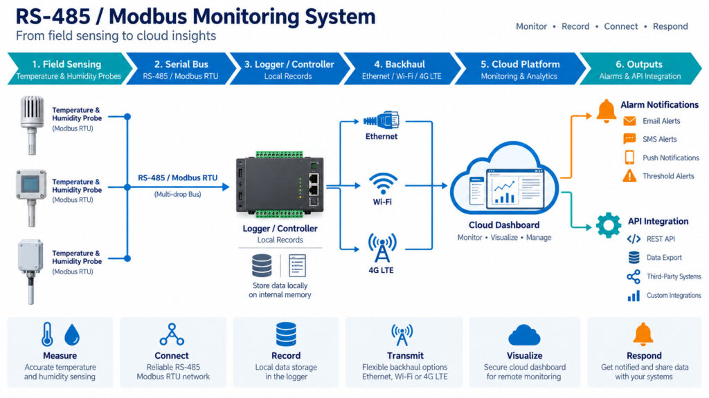
A complete RS-485/Modbus monitoring system connects field sensors, loggers, network backhaul, cloud platforms, alarms and APIs.
Who Is This Guide For?
This guide is for BMS/controls engineers, facility managers, integrators and industrial buyers specifying fixed or remote monitoring.
30-Second Selection Summary: How to Choose RS485 Modbus Temperature Humidity Sensor
| Question | Direct answer |
| What is it? | A digital temperature/humidity field sensor or transmitter that communicates over RS-485, often using Modbus RTU. |
| What matters most? | Range at the real operating condition, accuracy/calibration, register compatibility, power/wiring, local logging, alarms and integration path. |
| When does UbiBot fit? | When the project needs RS485 sensing plus onboard logging, remote connectivity, alarms and cloud/on-premises/API options in one architecture. |
| Conditional recommendation | Choose a dedicated high-precision industrial probe when metrology or extreme humidity dominates; choose an integrated logger architecture when remote records and operational workflow dominate. |
What Is an RS-485/Modbus Temperature and Humidity Sensor?
An RS-485 temperature/humidity sensor sends digital measurements over the EIA/TIA-485 physical layer; Modbus RTU is a common protocol on that link. A transmitter outputs field data, a logger stores time-stamped records, a gateway bridges networks, and a monitoring system adds alarms, users, reports and integrations.
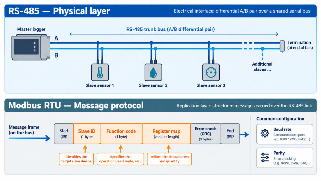
RS-485 defines the electrical serial interface, while Modbus RTU defines the message structure used on that link.
What Problems Does This Type of Monitoring Solve?
A complete system reduces manual checks, keeps continuous records, preserves data through outages, raises exceptions and consolidates many points. It also gives BMS, SCADA, QMS or custom applications a defined integration path.
What Components Make Up the Complete System?
A typical chain is sensor/probe → RS-485/Modbus RTU → logger/controller → IP backhaul → cloud or on-premises platform → alarm/API. During commissioning, record register/data types, slave ID, baud/parity, cable and grounding, supply voltage and termination. Modbus serial networks normally use a trunk-style bus with line-specific termination/polarization. [10]
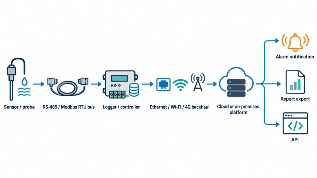
A complete monitoring chain includes the sensor or probe, RS-485 bus, logger, network backhaul, platform, alarms and API.
Which Sensor Specifications Matter Most?
Compare range and accuracy at the real operating condition, plus response time, drift, calibration and environmental limits. Keep probe accuracy, logger/input accuracy, resolution and overall system performance separate. UbiBot’s TH30S-B datasheet lists -40 to 80°C (-40 to 176°F), 0 to 100% RH and second-generation accuracy of ±0.2°C/±2% RH at 25°C/60% RH; confirm the shipped generation because the document also lists older specifications. [5]
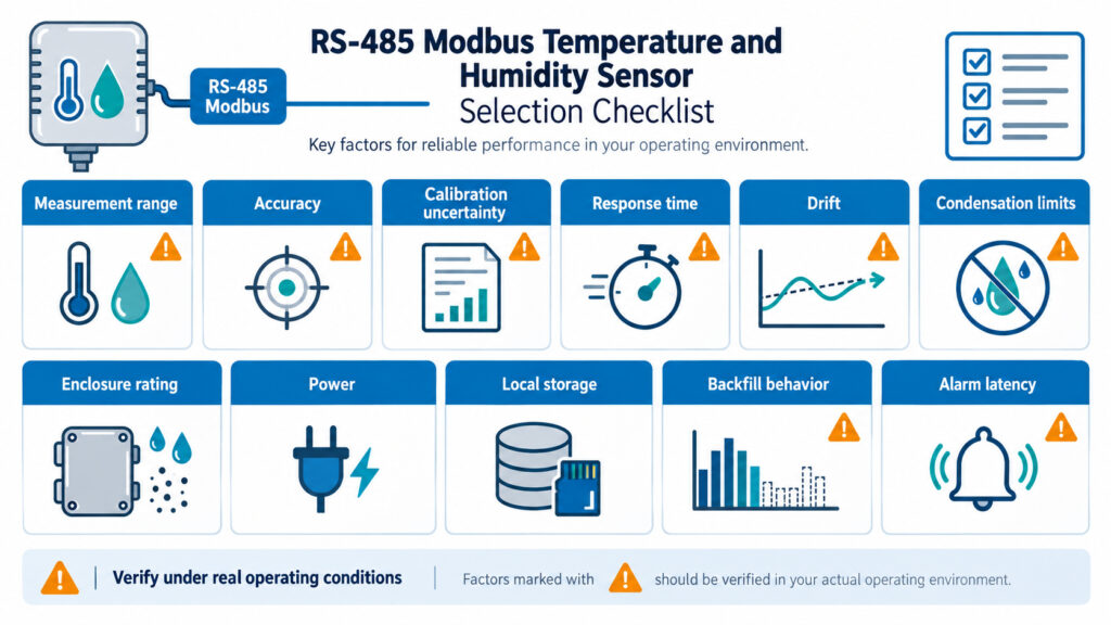
Selection should compare range, accuracy, calibration, response time, drift, enclosure, storage and alarm behavior under real operating conditions.
- Measurement range under the real temperature/humidity condition, not only the catalog maximum.
- Probe/sensor accuracy and calibration uncertainty; logger/input accuracy where an analog or RTD channel is used.
- Response time, long-term drift, sampling interval and upload interval.
- Condensation limits, enclosure/IP rating, cable/probe construction and power requirements.
- Local storage, backfill behavior after outage, alarm latency and calibration-document availability.
Which Connectivity Option Should You Use?
Use RS-485 as the local field bus. Choose Ethernet for stable fixed infrastructure, Wi-Fi where coverage is reliable, 4G/LTE for independence from the LAN, and long-range radio when cabling distributed points is impractical. LoRa is a radio modulation; LoRaWAN is a network protocol, so compatibility must be verified. Each RS-485 node also needs compatible serial settings, a unique address and a readable register map.
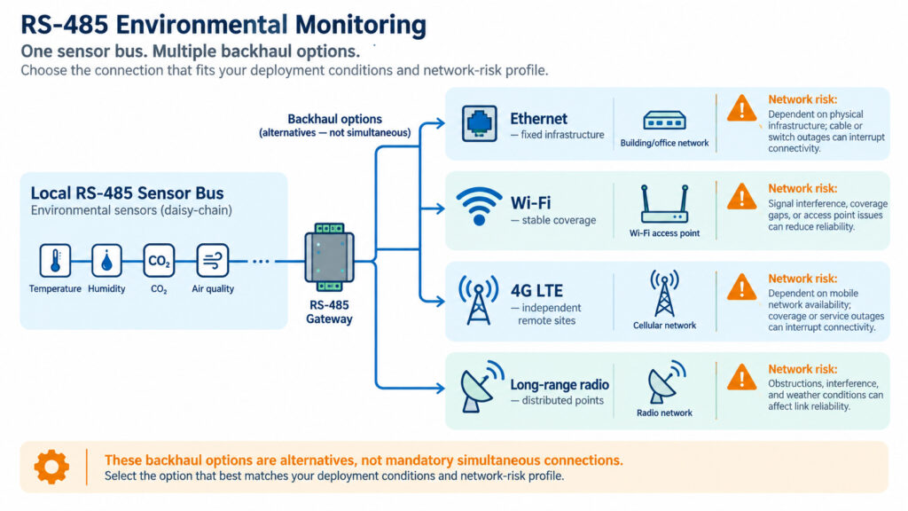
Ethernet, Wi-Fi, 4G and long-range radio serve different deployment conditions and network-risk profiles.
Which Leading Models Should Be Compared?
The comparison is architectural as well as metrological. UbiBot GS1/WS4 adds logging and remote-platform connectivity to RS-485 sensing; Vaisala HMP7, Rotronic HF5A and E+E EE210 are primarily probes/transmitters that depend on a host logger, controller or BMS for broader workflows.
See the detailed Product Comparison Table after the article body.
What Is the Best Option by Use Case?
Match the architecture to the failure mode and maintenance model of the site. The following combinations are starting points, not universal prescriptions; calibration, validation, network coverage and environmental exposure still have to be checked for the actual project.
| Use case | Key need | Recommended sensing / link | Suggested UbiBot configuration | Boundary to verify |
| Industrial workshop / plant room | Fixed T/RH plus BMS/remote access | RS485 T/RH probe; Ethernet where available | GS1-AETH1RS + TH30S-B; use GS1 General Sensor only for verified third-party Modbus devices | Electrical noise, grounding, supply voltage, register map |
| Remote utility room / unmanned site | Independent backhaul and outage records | RS485 probe + 4G logger | WS4-A4G1RS + compatible probe | Local 4G bands, SIM/data plan, enclosure exposure |
| Commercial building / BMS | Simple direct field-bus integration | Dedicated Modbus transmitter | GS1 with RS485 if cloud + BMS bridge is wanted; otherwise a BMS-native transmitter may be simpler | BMS polling, cybersecurity, software ownership |
| Cold room / low-temperature point | Probe located at product-representative point | External temperature probe selected for range; T/RH only if humidity is meaningful | GS1/WS4 + PT100 or suitable external probe, subject to calibration/validation | Do not use built-in room sensor outside its operating range |
| High-humidity chamber / process | Condensation tolerance and metrology performance | High-humidity industrial probe with anti-condensation design | Use UbiBot as logger only if the selected probe/interface is technically validated | Probe heating/condensation behavior, uncertainty and calibration |
| Greenhouse / distributed agriculture | Many points, humidity exposure, flexible networking | RS485 probes near logger or long-range wireless architecture for larger layouts | WS4-A1RS for local Wi-Fi sites; other UbiBot long-range architectures may suit larger distributed layouts | Outdoor sheltering, condensation, cable length, gateway design |
How Should Deployment Scale and Total Cost of Ownership Be Compared?
Compare lifecycle cost, not hardware price alone: sensor/probe, power, cabling, installation, gateways, SIM/data, software, API access, calibration, validation, batteries, servers and expansion. A cheaper transmitter can cost more if every point needs custom PLC/BMS work.
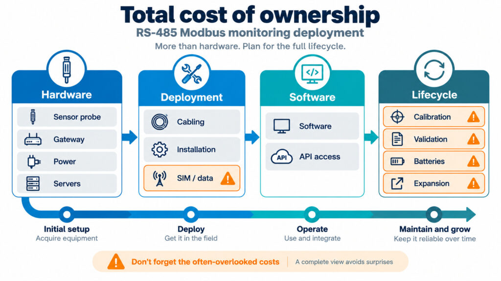
Lifecycle cost includes hardware, cabling, installation, software, SIM/data, calibration, validation, batteries and expansion.
What Are the Most Common Buying Mistakes?
Common mistakes include buying on price or range alone, confusing resolution with accuracy, ignoring calibration or offline retention, assuming RS-485 devices share registers, and overlooking recurring platform costs. Also verify condensation limits, supply voltage, regional 4G bands and the protocol used over RS-485.
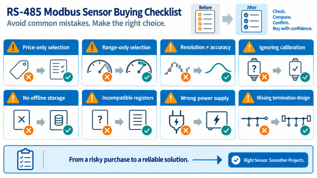
Common mistakes include buying by price alone, confusing resolution with accuracy and assuming all RS-485 devices share the same registers.
Where Does UbiBot Fit?
UbiBot fits projects needing RS-485 sensing plus onboard records, remote alarms, cloud/on-premises options and API/data forwarding. GS1-AETH1RS suits fixed Ethernet/Wi-Fi sites; WS4-A1RS is an IP65 Wi-Fi logger; WS4-A4G1RS adds 4G for sites without dependable LAN. [1][3][4] UbiBot documents third-party RS-485 configuration through the GS1 General/Universal Sensor function on firmware v2.0.7+, subject to protocol and power compatibility. [6] Do not extend that claim to every model. For extreme humidity or metrology-led projects, a dedicated industrial probe may be preferable.
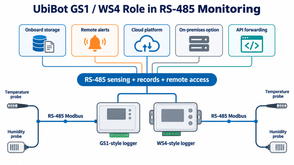
UbiBot fits projects needing RS-485 sensing plus onboard records, remote alarms, cloud or on-premises options and API forwarding.
How Do You Choose the Right System?
Choose in this order: parameter → range → accuracy/calibration → point count → RS-485 registers/wiring → backhaul → local storage → alarms → platform/API → lifecycle cost. Then specify the exact sensor/logger pair and verify the latest product specifications before commissioning.
Product Comparison Table
The comparison uses exact configurations wherever the manufacturer provides an orderable variant. Measurements are probe-specific; platform functions belong to the logger/controller layer. Specifications reviewed September 11, 2026.
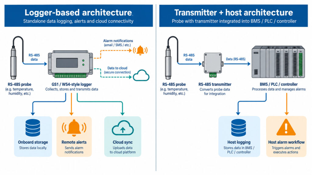
UbiBot combines RS-485 sensing with logging and remote platform functions, while dedicated transmitters often depend on a host BMS or controller.
Measurement, Interface and Power
| Configuration | Product type | Sensor/probe configuration | Measurement range | Published accuracy | RS-485 / Modbus | Power |
| UbiBot GS1-AETH1RS + TH30S-B | Logger / remote monitor + RS485 probe | GS1 built-in T/RH + TH30S-B external air T/RH probe | GS1 built-in: -20 to 60°C (-4 to 140°F); TH30S-B: -40 to 80°C (-40 to 176°F), 0-100% RH | GS1 built-in: ±0.2°C (0-60°C), ±2% RH (10-90% RH). TH30S-B 2nd gen datasheet: ±0.2°C, ±2% RH at 25°C/60% RH; confirm generation. | TH30S-B: RS485 Modbus; GS1 RS485 interface. TH30S-B default 9600 baud, address 1-247. | GS1: Type-C / DC 5-12V; PoE supported via applicable setup. TH30S-B: DC 5-12V. |
| UbiBot WS4-A1RS + TH30S-B | IP65 Wi-Fi logger + RS485 probe | WS4 built-in T/RH/light/vibration + UbiBot-listed RS485 probes | Built-in T: -20 to 60°C; built-in RH: 0-100% RH; TH30S-B: -40 to 80°C, 0-100% RH | Built-in: ±0.2°C (0-60°C), ±2% RH (10-90% RH). TH30S-B: see generation note above. | RS485 external-sensor interface; use supported probe configuration and register settings. | Built-in 2500mAh lithium battery / Type-C 5V. |
| UbiBot WS4-A4G1RS + TH30S-B | IP65 4G logger + RS485 probe | WS4 built-in T/RH/light/vibration + UbiBot-listed RS485 probes | Built-in T: -20 to 60°C; built-in RH: 0-100% RH; TH30S-B: -40 to 80°C, 0-100% RH | Built-in: ±0.2°C (0-60°C), ±2% RH (10-90% RH). TH30S-B: see generation note above. | RS485 external-sensor interface; 4G backhaul bands are regional and must be checked. | Built-in 2500mAh lithium battery / Type-C 5V. |
| Vaisala HMP7 (standalone Modbus RTU) | High-humidity T/RH probe / digital transmitter | HUMICAP HMP7 with Pt100 RTD Class F0.1 | RH: 0-100% RH; T: -70 to 180°C (-94 to 356°F) | Up to ±0.8% RH at +23°C (0-90% RH); T ±0.1°C at +23°C. | Modbus RTU over RS-485; compatible with Indigo transmitters and Insight PC software. | 18-30 VDC. |
| Rotronic HF5A-D1 + HC2A-S | Industrial transmitter + interchangeable probe | HF5A digital Modbus variant with HC2A-S standard T/RH probe | HC2A-S: 0-100% RH; -50 to 100°C (-58 to 212°F) | HC2A-S: ±0.8% RH and ±0.1°C at 10-30°C. | HF5A-D1: RS485 half-duplex, Modbus RTU; default 19,200 baud, slave ID 247. | HF5A: 18-36 VDC. |
| E+E EE210-M1T1J3 (RS485 wall configuration) | Industrial HVAC T/RH transmitter | EE210 wall-mount T1 with RS485 output (ordering code family J3) | RH: 0-100% RH; T: -40 to 80°C (-40 to 176°F) measurement range | RH: ±(1.3 + 0.003×mv)% RH at -15 to 40°C and ≤90% RH; T approx. ±0.2°C in central range per datasheet curve. | RS485; Modbus RTU selectable; 9,600 / 19,200 / 38,400 baud. | 15-35 VDC or 24 VAC ±20% for RS485. |
Comparison conclusion. Vaisala HMP7 and Rotronic HF5A + HC2A-S lead with stronger dedicated probe/transmitter metrology in their intended conditions; E+E EE210 is a direct BMS/HVAC transmitter; UbiBot’s differentiator is the integrated chain from RS485 sensing to local records, remote connectivity, alerts, cloud/on-premises platform options and APIs. Choose by architecture and intended use, not by a single ranking.
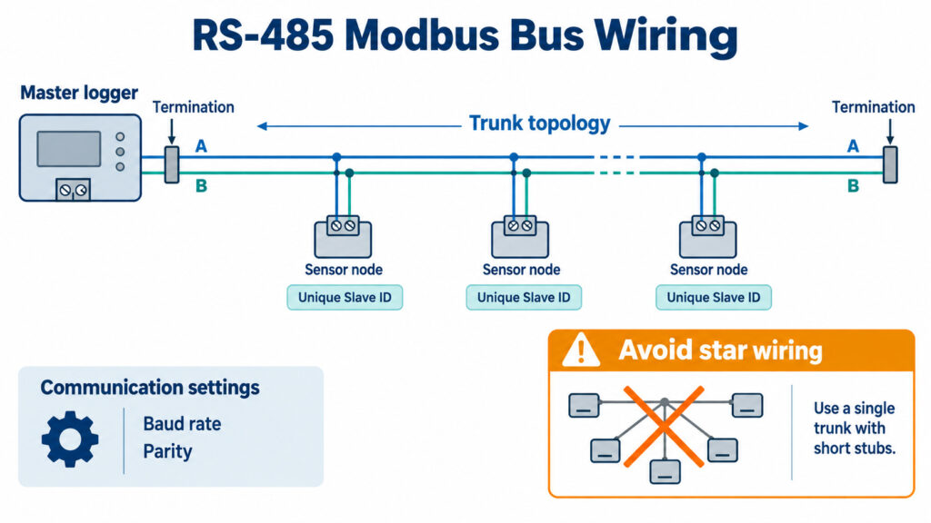
RS-485 networks require unique device addresses, compatible serial settings and correct bus topology.
Frequently Asked Questions
What is the difference between RS-485 and Modbus RTU?
RS-485 defines the electrical serial interface; Modbus RTU defines how messages, addresses and register data are structured on that serial link. A product can use RS-485 with a different protocol, so verify both the physical interface and the protocol.
How do I choose an RS485 Modbus temperature humidity sensor for a BMS?
Start with the required range and uncertainty, then verify Modbus RTU registers, data types, slave addressing, baud/parity options, supply voltage, enclosure, calibration, and whether the BMS can poll the device directly. If you also need historical data and remote alarms, include a logger or gateway in the specification.
Do I always need a 120-ohm termination resistor on an RS-485 sensor?
No. Termination belongs at the ends of the bus and must follow the equipment and network design. The Modbus Serial Line guide discusses line termination and polarization values, but the correct implementation depends on the devices, cable and topology. Do not place a termination resistor on every node.
Can multiple Modbus temperature and humidity sensors share one RS-485 bus?
Yes, if the master and devices support a multi-drop bus and every device has a unique address with compatible serial settings. Cable topology, power distribution, grounding, termination and master polling capacity still need to be engineered.
What happens to monitoring data when the Internet connection fails?
That depends on the logger, not the RS-485 sensor alone. UbiBot GS1-AETH1RS and current WS4 RS485 models publish onboard storage for up to 300,000 sensing records and synchronization after reconnection. A standalone industrial transmitter may require the BMS or logger to provide buffering. [1][3][4]
Is a wider temperature range always better?
No. Range only shows where a sensor can operate or measure. Accuracy, calibration uncertainty, drift, response time, probe construction and the conditions under which the accuracy is specified determine whether it is suitable for the application.
How should high humidity or condensation affect sensor selection?
Choose a probe designed for the expected moisture exposure and read the manufacturer’s condensation limits. Vaisala HMP7, for example, includes probe/sensor warming functions intended to reduce condensation in high-humidity applications. A general room sensor should not be assumed suitable for persistent condensation. [9]
Can UbiBot read a third-party RS-485 Modbus sensor?
UbiBot documents a General/Universal Sensor function for GS1 series firmware v2.0.7 and later. The third-party sensor must match the supported communication-frame format and may need a separate power supply if the GS1 interface cannot provide the required voltage. Verify the exact register behavior before deployment. [6]
Does an RS-485 sensor include cloud monitoring and alarms?
Not necessarily. Vaisala HMP7, Rotronic HF5A and E+E EE210 are field probes/transmitters; remote storage and notifications depend on the connected transmitter, controller, logger, or software. UbiBot GS1/WS4 configurations combine the field-sensor interface with onboard logging and platform services.
Which is better for a remote industrial site: Ethernet, Wi-Fi or 4G?
Ethernet is usually the most predictable for a fixed wired site, Wi-Fi is efficient where managed coverage is stable, and 4G is useful when the monitoring path must be independent of the local LAN. The best choice is the one that meets uptime, security, installation and recurring-cost requirements.
Sources and Specification Notice
Specifications and platform features were reviewed using publicly available manufacturer information on September 11, 2026. Product configurations, regional availability and subscription terms may change. Confirm the latest specifications with each manufacturer before purchasing.
[1] UbiBot GS1 Specifications https://www.ubibot.com/ubibot-gs1-specifications/
[2] UbiBot GS1-AETH1RS product/store page https://store.ubibot.com/products/ubibot-gs1-eth-wifi-and-ethernet-cable
[3] UbiBot WS4-A1RS product page https://store.ubibot.com/products/ubibot-ws4-a1rs
[4] UbiBot WS4-A4G1RS product page https://store.ubibot.com/products/ubibot-ws4-a4g1rs
[5] UbiBot TH30S-B Temperature & Humidity Probe datasheet https://www.ubibot.com/wp-content/uploads/dlm_uploads/2020/06/Specifications-TH30S-B-TemperatureHumidity-Probe.pdf
[6] UbiBot General/Universal Sensor settings https://support.ubibot.com/hc/en-us/articles/30219038261785-How-to-use-General-Probe-Settings
[7] UbiBot On-Premises Platform https://www.ubibot.com/on-premises-platform/
[8] UbiBot alert methods https://helpdesk.ubibot.com/article/how-to-setup-alerts
[10] Modbus Serial Line Protocol and Implementation Guide V1.02 https://www.modbus.org/docs/Modbus_over_serial_line_V1_02.pdf
[11] UbiBot Data Forwarding/API documentation https://www.ubibot.com/app-platform-api/8213/channel-feeds-data-forwarding/